Daily Image
19-07-2007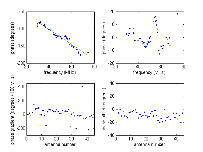
What Dunnit?
| Submitter: | Stefan Wijnholds |
| Description: | Knowledge of the phase and delay differences introduced by electronic components is a key factor in the success of radio interferometers like the WSRT and LOFAR. For the latter, a telescope under development, we also want to disentangle the contributions of the individual components such as antennas, amplifiers, cables and receivers. Fortunately, each component leaves its own traces in the calibration data, a fact that we are happy to exploit. The upper left panel depicts the phase of one of the low band antennas in CS10. The most predominant feature is the phase slope produced by time delays in the system. Once the delays are removed, a residual phase remains, which typically behaves as shown in the upper right panel. The phase changes around 55 MHz are the signature of the antenna resonance. The plot in the bottom left corner summarizes the phase gradient over the full band (100 MHz) indicating a RMS phase variation of about 30 degrees or, equivalently, 0.8 ns. The deviating values are caused by additional delays introduced in the digital processing at the station. Finally, the plot in the lower right panel summarizes the frequency independent phase offsets demonstrating that the RMS phase difference between the receiver units is about 3 degrees. |
| Copyright: | LOFAR |
| Tweet |  |