Daily Image
14-10-2011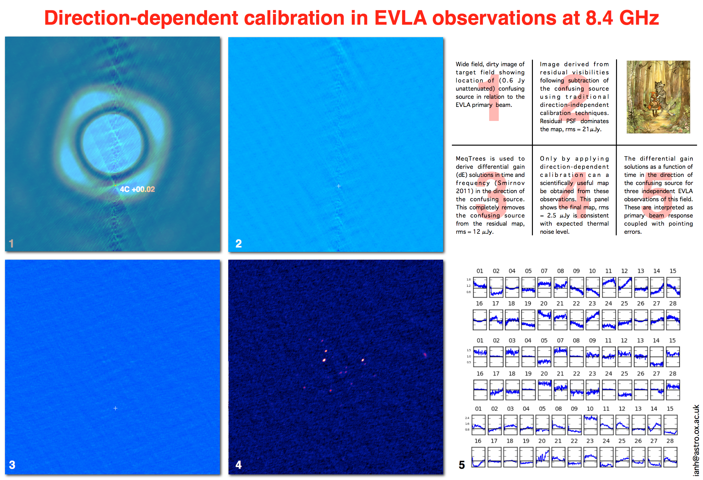
Direction-dependent calibration in EVLA observations at 8.4 GHz
| Submitter: | Ian Heywood |
| Description: | The differential gains algorithm (Smirnov 2011) implemented in the MeqTrees software package (Noordam & Smirnov 2010) has been successfully applied to data from the Expanded Very Large Array (EVLA) in order to model and subtract a particularly troublesome confusing source that traditional calibration techniques could not deal with. As can be seen in Panel 1 the confusing source was situated between the first null and the first sidelobe of the primary beam (depending on the channel frequency). The partially blocked aperture of the Cassegrain optics of the EVLA antennas gives rise to the azimuthal structure in the first sidelobe. This pattern rotates on the sky as the observation progresses due to the alt-az mount, thus imparting apparent transient behaviour in the source. Panel 2 shows the best residual map from the subtraction of a clean component model following the standard gain and bandpass calibration. Since this field is equatorial the PSF has strong north-south sidelobes and the residual garbage from the confusing source swamps the science targets in the centre of the map. Extra (differential) complex gain terms are derived both in frequency and time by solving against a sky model that consists of a single point source at the location of the confusing source. In this regime the technique is analogous to peeling. The model visibilities resulting from this process are subtracted from the observed visibilities, and the confusing source is now removed from the resulting map without trace. This technique is applied to each of the independent 'scheduling blocks' that make up the full EVLA observation and the resulting combined map is shown in Panel 4. Only via the use of the differential gains technique could the science goals of this observing program be met. The background level of the final map is 2.5 micro-Janskys, consistent with the expected thermal noise. These data were presented at the recent 3GC-II workshop in Portugal and provoked a lot of discussion, particularly with regards to the interpretation of the gain solutions, shown as a function of time for each antenna within three independent scheduling blocks in Panel 5. Since at 8.4 GHz the dominating direction-dependent effect is likely to be the beam gain, one would expect the solutions to be similar from antenna to antenna. Coupling a beam model from Walter Brisken's CASSBEAM software with a MeqTrees simulation provided the answer. The simulation incorporated a pointing error consistent with the assumed ~10" pointing accuracy of the EVLA. When a strong source is in a part of the beam with steep gain gradients (e.g. between the first null and first sidelobe) such pointing errors are enough to ensure that each antenna has significantly different beam responses in the direction of that source. These results are reassuring. Even a source in the Worst Possible Place can be solved for as the smoothness of the solutions and the final maps attest. Nonetheless the gain solutions do contain some intriguing features (e.g. antenna 20 on the final row) which are yet to be explained. EVLA observations of a suitable test field with a group of strong point sources scattered across the beam are very much high on the wish-list. |
| Copyright: | Ian Heywood |
| Tweet |  |