Daily Image
28-11-2011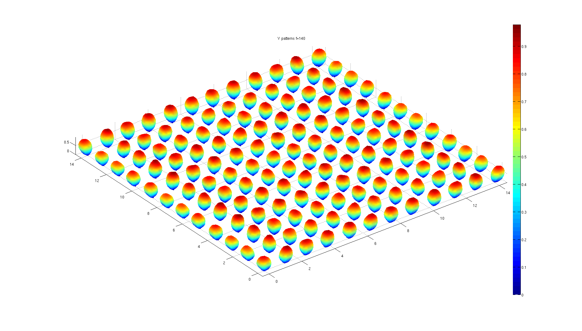
HBA embedded element patterns
| Submitter: | Dion Kant |
| Description: | The picture looks like a collection of potatoes, nicely organised on a grid. In reality, they are the embedded element patterns of 12x12 antenna elements, embedded in a 3x3 configuration of LOFAR HBA tiles. Each tile has 32 antenna elements, 16 of which are oriented along along the X-axis and 16 along the Y-axis. They are arranged in a 4x4 grid of co-located pairs. The 15 cm gaps between the tiles are included in the model. The simulation is for a frequency of 140 MHz. In this simulation, each element is attached to a voltage source with a source impedance of 50 Ohms. One voltage source, connected to an Y-oriented element, is set to 1 V. All other sources are set to zero. The resulting current distribution is calculated, and the far-field embedded-element pattern is derived from these currents. In the picture, the resulting pattern is plotted at the position of the element connected to the active voltage source. This procedure is repeated for all Y-oriented elements. The so-called "embedded-element patterns" include all the couplings to surrounding elements, and all finite-array effects. Since the electric field of one pattern depends linearly on the voltage of the corresponding generator, beam patterns of the entire array may be calculated by simple super-position of the element patterns. Full electromagnetic wave simulations on the model are performed by commercial WIPL-D software. The latter uses an efficient implementation of the well-known method-of-moments. It may even allow us to do the calculations for a 24-tile LOFAR station with 768 antenna elements. The 2x2 Jones matrices resulting from these simulations will be used to enhance the LOFAR HBA calibration. |
| Copyright: | GPL V2.0 |
| Tweet |  |