Daily Image
16-10-2012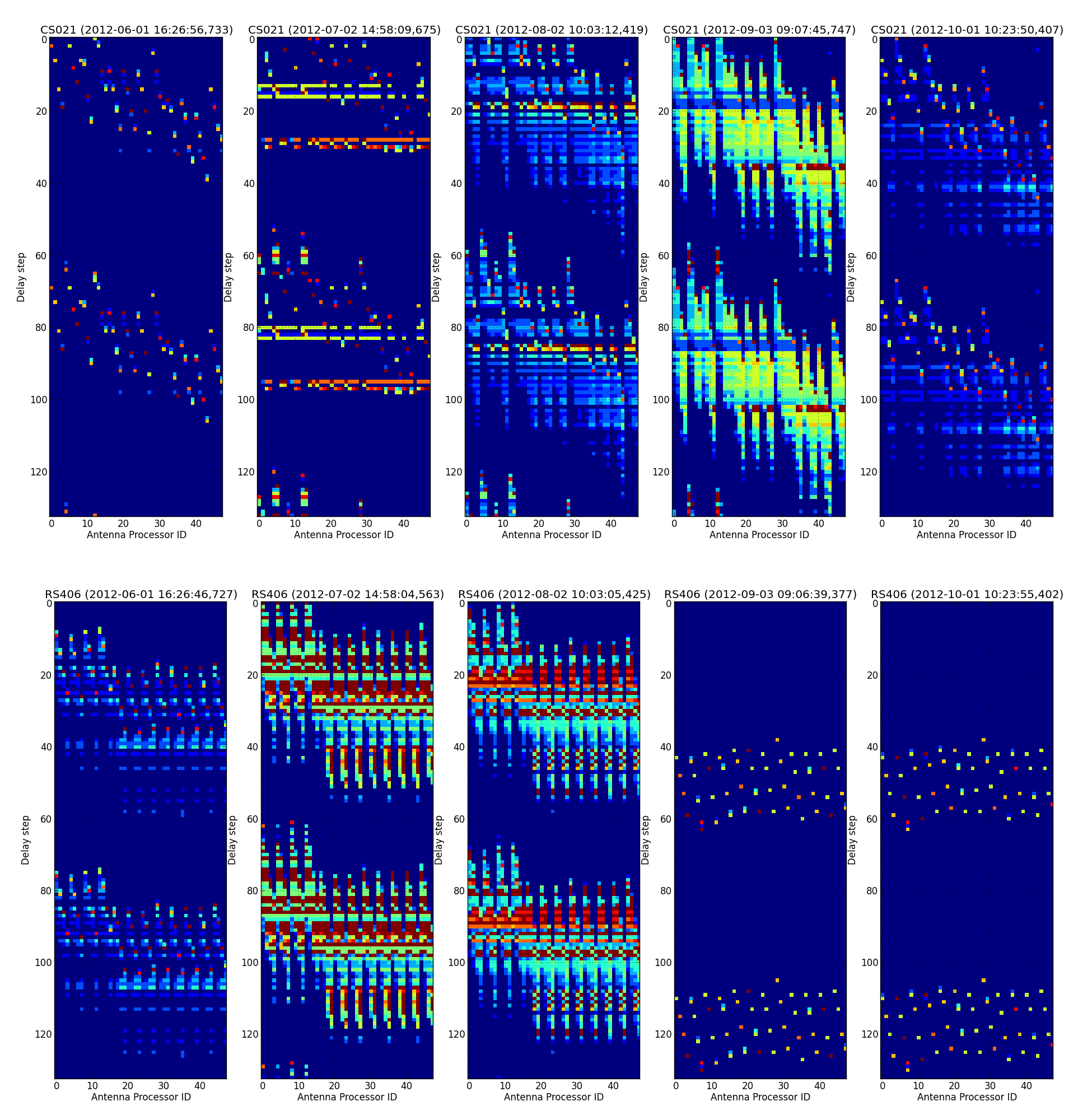
LOFAR receiver synchronization
| Submitter: | Michiel Brentjens |
| Description: | The receivers in a LOFAR station sample the data 200 million times per second. The first 200 MHz sample after the first Pulse Per Second (PPS) arriving at the receiver is sample 0. They must of course all agree. It is also essential that the PPS arrives at the same time everywhere. Uncertainties arise when the rising flank of the PPS coincides with the rising flank of the 200 MHz clock signal. A one clock pulse offset puts an antenna at a 180 degree phase error at 100 MHz observing frequency, totally canceling the signal of another antenna! We do PPS tuning to determine a delay correction to the arrival of the PPS to reliably select the first 200 MHz pulse. These extra delays are in steps of 75 picoseconds, and are shown on the vertical axis of the plots. The horizontal axis shows the antenna number, and the colour is the number of failures to reliably detect the first 200 MHz pulse. Dark blue is no failures, which is good. The five columns are recorded at June 1, July 2, August 2, September 3, and October 1 2012. The top row is station CS021, the bottom row RS406. It turns out that LOFAR's Rubidium clocks are not good enough. The PPS flanks are sometimes irregular, the PPS can jitter forward and backward by a couple nanoseconds, and the three output ports of the clock, which each feed a different set of 16 antennas, can drift up to 6 ns with respect to each other. Gijs Schoonderbeek and several others from R&D have developed the SyncOptics boards to counter these effects. On Friday August 31, RS406 received its SyncOptics board. Can you see this in the plots? The core stations are outfitted in the second and third week of October. |
| Copyright: | (c) ASTRON 2012 |
| Tweet |  |