Daily Image
17-01-2020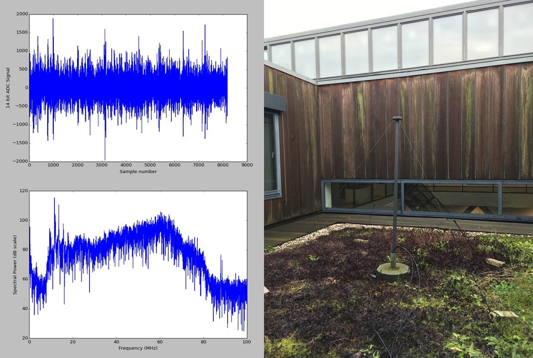
First LOFAR2.0 LBA Spectrum
| Submitter: | Jonathan Hargreaves / Gijs Schoonderbeek |
| Description: | “Well begun is half done” (een goed begin is het halve werk). In the first working week of 2020 we measured the first LOFAR Lowband Antenna (LBA) spectrum captured with a UniBoard2, the new processing board for LOFAR2.0. As shown in the image an LBA antenna is placed on the patio near the digital lab. This antenna is connected to a LOFAR1.0 Receiver Unit (RCU) and via an ASTRON-developed Analog to Digital converter (ADC) prototype board connected to UniBoard2. The samples are received and captured in one of the UniBoard2's field programmable gate arrays (FPGA), then read out by the control PC resulting in the plot. Although this is only a first small step it helps the LOFAR2.0 design teams to work together in an early stage to design the new LOFAR2.0 system. All LOFAR2.0 competences (systems engineering, analog design, firmware design, mechanical design and software control) were necessary to create this important first step. By this demonstration one of the technical risks within the LOFAR2.0 station is mitigated, because in LOFAR2.0 we use instead of a parallel a serial interface between the receiver and the digital processing. Below some more technical details about the setup for curious engineers. For this measurement a LOFAR1.0 LBA antenna is used. The antenna signal is amplified by ~20 dB in the 10-80 MHz mode of the RCU. A 14 bit Analog Devices ADC digitizes the analog signal, and transmits the serial digital data stream using the JESD204B protocol. This data is received by an Intel Arria10 FPGA on UniBoard2 where it is stored in an 8192 samples deep data buffer. A 1 GbE control interface is used to read-out the data. Finally, a python script is used to plot the raw and frequency data. |
| Copyright: | ASTRON |
| Tweet |  |