Daily Image
12-09-2022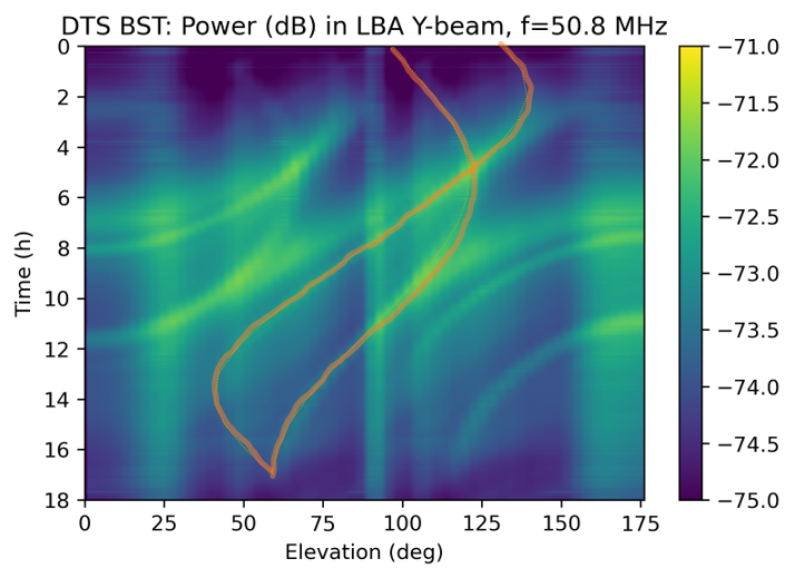
LOFAR2.0 team achieves digital beamforming
| Submitter: | Arno Schoenmakers, on behalf of the LOFAR2.0 Development team |
| Description: | An essential ingredient of any phased array antenna array is the ability to maximize sensitivity in the desired direction, aka beamforming. This mimics the limited viewing angle that is normally provided by steering a parabolic dish. The advantage of phased array antenna arrays is that in essence no moving or rotating parts are necessary. The process of pointing a phased array is complicated, and it is a challenge to verify the direction of maximum sensitivity actually, and whether the system tracks a source as required. In LOFAR, the beamforming functionality is implemented in two steps: analog and digital beamforming. We call the process of pointing the station beam 'digital beam forming', as the corrections to achieve this are all done in the digital signal domain. It involves coordinate transformations, calculations of a large number of so-called beam-weights and sending these to the Uniboards (for LOFAR2.0), in time, so these can be applied to the proper data samples. It requires that software, firmware, servers, network and timing equipment work together in a coordinated and strictly synchronized fashion. The process has many interfaces and thus many points of possible failure. The sky image shown here proves that we have mastered this complex orchestration now also in LOFAR2.0, using the DTS-Outside test system in the ASTRON backyard. It shows the recorded signal strength in a single frequency band plotted in a time vs. elevation plot. As we only have a 1-D antenna array with 9 antennas, we created a series of digital beams covering the sky in 1 dimension. This was then transformed into the image shown above. When we superposition the expected positions of the two strongest sources in the sky, Cas-A and Cyg-A, we can see that we have detected them, and have been able to follow their path over the array. All the other lines and arcs are due to the so-called grating response, caused and amplified by the equidistant linear layout of our small LBA array, and to aliasing. We, the LOFAR2.0 development team, are very happy to show this great result: the beamformer is working correctly. The next step is to repeat such observations using a different antenna layout pattern, so we can more accurately determine that the pointing direction is indeed where it should be. This we will do once we have setup the DTS equipment at LOFAR station CS001, which is planned for early October |
| Copyright: | ASTRON |
| Tweet |  |