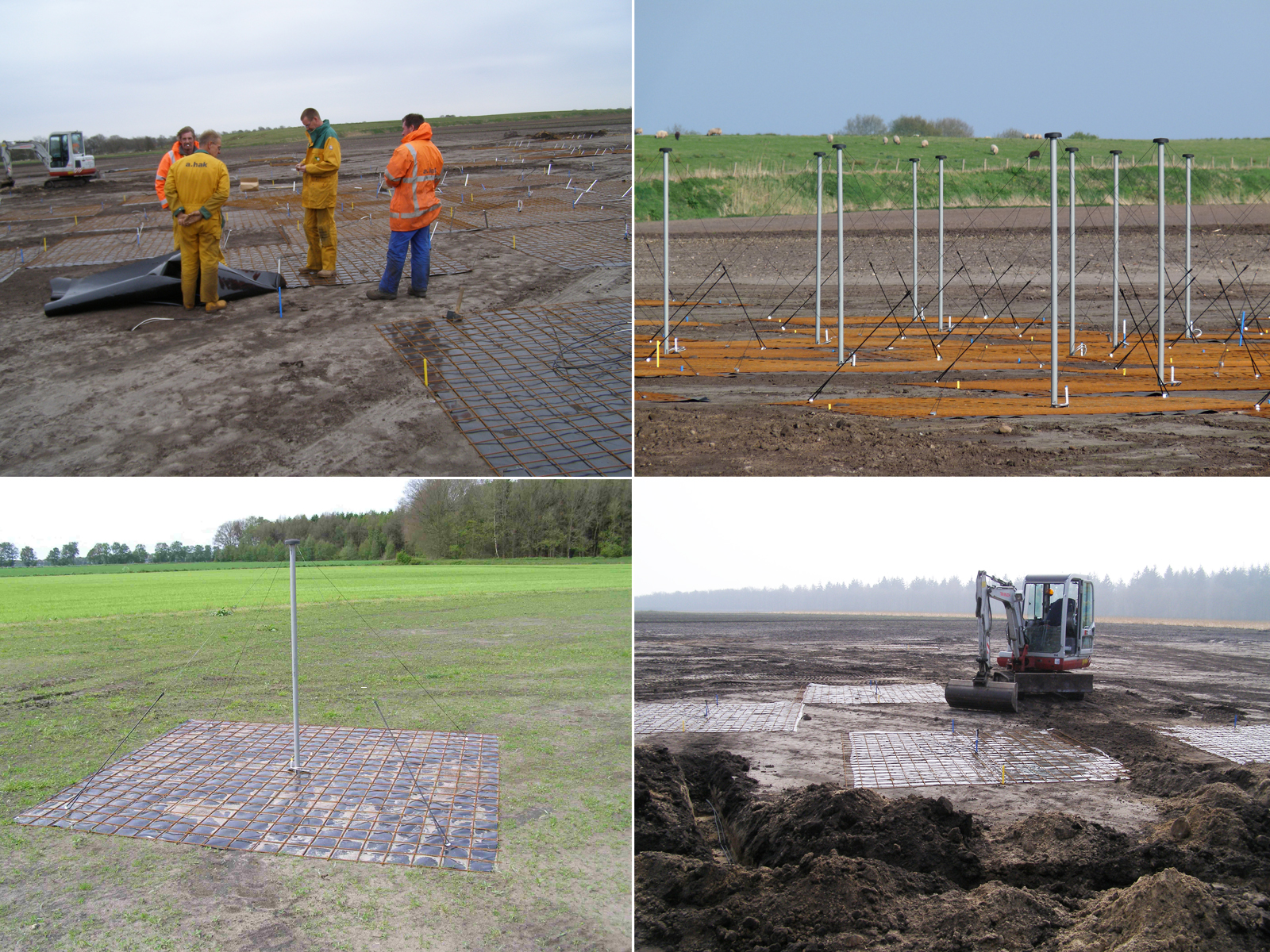
| Description: | Each LOFAR station has 96 Low Band Antennas (LBAs). In the Netherlands these are connected to 48 receivers, which means that half the 96 antennas can be used at any time. In this way, different configurations can be used at low and high frequencies in the LBA band which runs from 10 to 80 MHz. The antennas are distributed in a roughly circular area, 70 m in diameter. The signals are detected using the wires that emanate from the black block at the top of PVC pole which contains the Low Noise Amplifier, which amplifies the signals so that they can be transported to the cabinet, where they are digitised in the receiver. The antenna wires are connected to a piece of cord on one side and a rubber spring on the other side. These are fastened to the ground using anchors. Because each antenna receives two orthogonal polarisations, the whole structure is stable. The antenna ground plane is a steel mesh that is normally used to reinforce concrete. Beneath the mesh is a mat which is there to prevent vegetation from covering the antenna. Note that the antennas are not fastened to the ground plane. Erecting a field of LOFAR LBAs only takes a couple of days, once the preparations (flattening of the field and laying of the cables) have been completed. |