Roadmap for the LOFAR Instrument Development Program
 The International LOFAR Telescope is a complex system and has many stakeholders with different needs. Also, we are about to transition LOFAR2.0 from the development to the commissioning phase. Together with the stakeholders we need to plan the various validation testing, from the operational side (operators, maintainers, science support) to development teams, hardware and software suppliers, management, and of course scientific teams such as pulsar timing, imaging, transients, cosmic rays, lightning, and others.
Each of them has a different need and without keeping a high-level overview of the work, functionality may not be delivered, delivered too late or become very costly to implement. We want to reduce the risk of not meeting expectations.
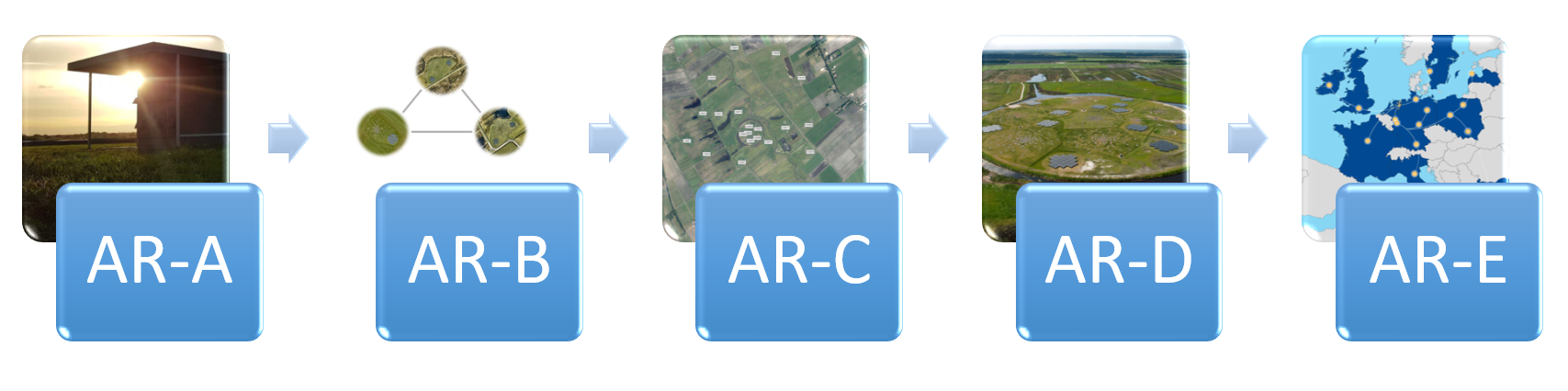
Therefore, we are developing a roadmap to have a single place where all activities related to LOFAR are identified. The plans are aligned using a series of Array Releases with increasing complexity to integrate (and learn) as early as possible. Array Release A (AR-A) is the first minimal and end-to-end system with a single LOFAR2.0 station, controlled by the Telescope Manager and sending data to the Central Processor. Array Release B (AR-B) has three LOFAR2.0 stations and also integrates further with the systems used by operations. The number of stations increase to Array Release AR-D and AR-E with all Dutch stations and all European stations upgraded. The Array Releases A to E form a common language throughout the LOFAR development and commissioning phases to keep overview and have realistic plans.
Deep sub-arcsecond wide-field imaging with LOFAR
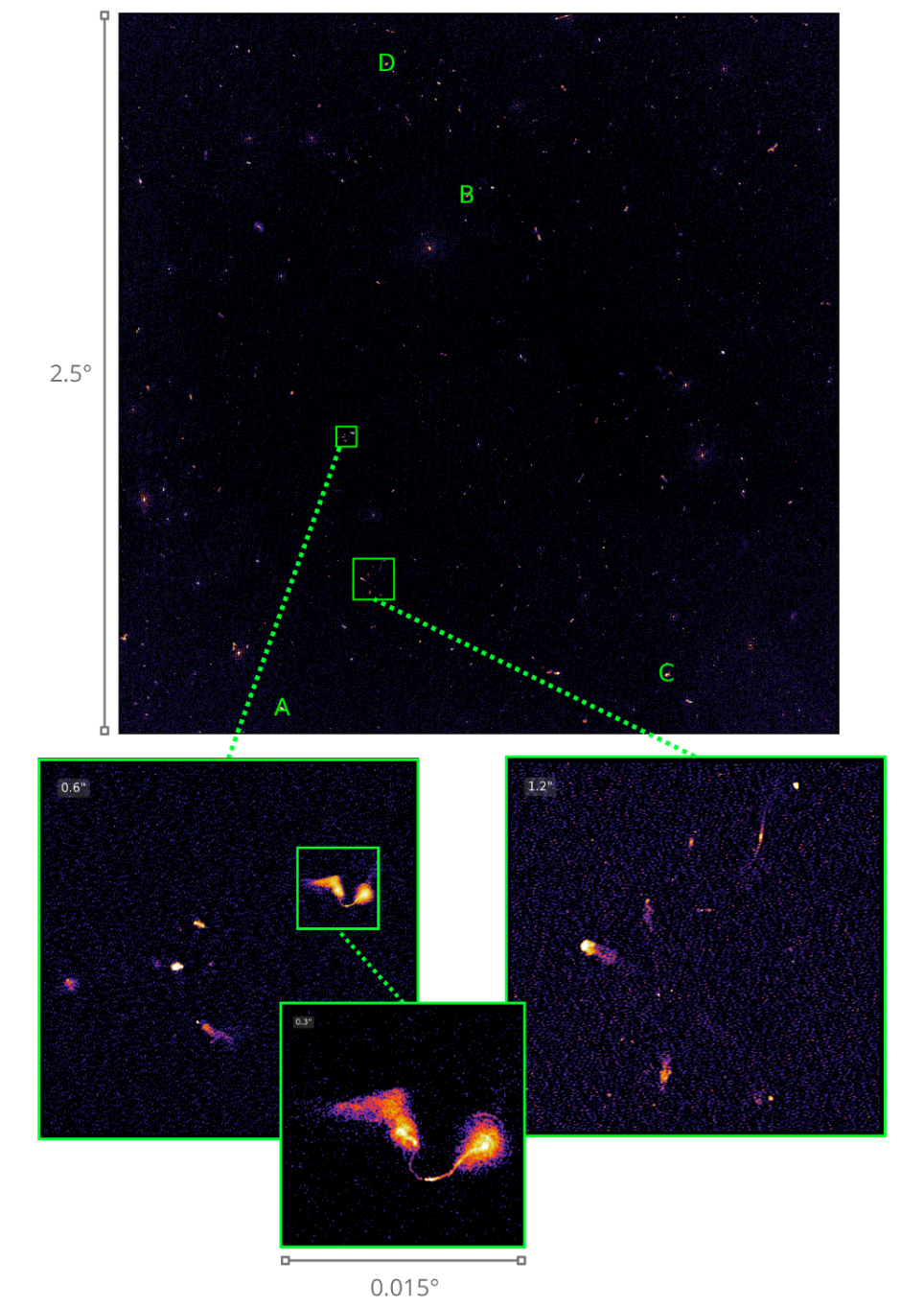
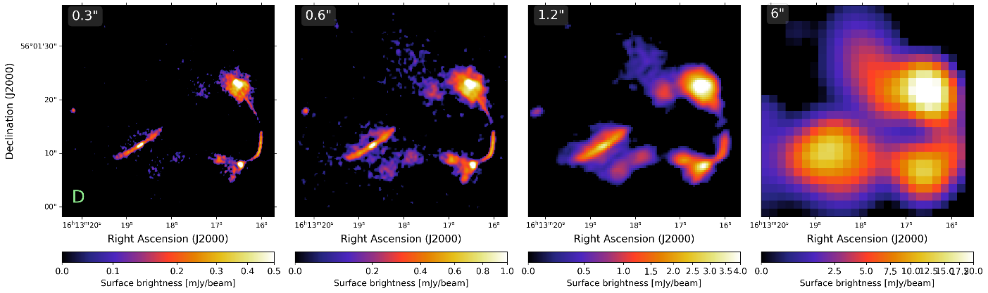
We present the deepest sub-arcsecond wide-field image of ELAIS-N1 at 144MHz to date, accomplished by processing 32 hours of international LOFAR data. This image reveals structures of various astronomical objects at a resolution of 0.3”. The depth, with a sensitivity of 17 μJy/beam near the pointing center, was obtained in approximately 9 times less observing time than would have been necessary with just the Dutch LOFAR high-band antennas. Our efforts mark a significant step in advancing us towards the development of a robust and fully automated LOFAR VLBI wide-field imaging pipeline. This pipeline is essential for efficiently processing upcoming sub-arcsecond northern sky surveys, facilitating the study of the low-frequency universe at the smallest angular scales.
DANTE
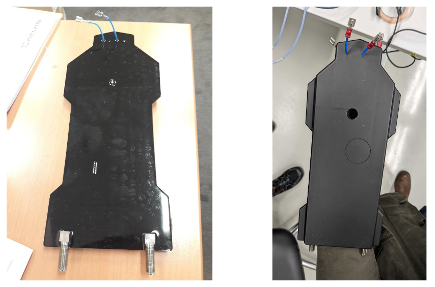
At the end of 2023, the AHBAFE prototypes developed in DANTE, that were first tested in one tile in CS001, were potted to determine any impact on performance from adding this protective layer (Figure 1). Unfortunately, we could quickly confirm that once the boards were potted, they were not performing as they did before. The potting material induces instability in the Low Noise Amplifier (LNA) and this is a real stopper. An unstable design means that when producing thousands of boards, we will have a very large spread in performance with the risk that a large fraction of the boards is useless.
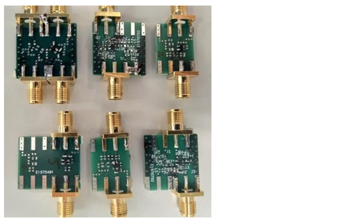
The task of determining the cause and nature of this issue is not easy since once the boards have been covered in the protective layer, their components are no longer accessible. The team had to come up with clever ideas to first reproduce the problem to then find a solution. Once we could identify the root of the problem being the LNA, we could focus on that block. Figure 2 shows several of the LNA test boards produced.
As of today, the team has found a configuration in components and layout that provides an unconditionally stable LNA. This solution has been now tested in simulations and in the coming weeks we will produce a test board that will be potted to confirm that the problem is solved.
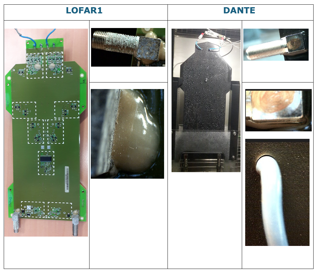
In parallel, we run an accelerated lifetime test on the LOFAR HBAFE and the DANTE AHBAFE. During this test, the samples are subjected to humidity and temperature cycles including some freeze cycles. The tests run for ~1500 hours which is equivalent to ~7.5 years in real time. The LOFAR HBAFE is tested to confirm that the method chosen can reproduce the failures observed in the field.
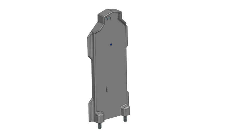
The tests show that every geometry bridging the potting from the PCB to the outside environment is a potential risk for water entering the PCB. Due to a difference in thermal expansion between the potting material and the geometry that is interfacing with the outside environment, minuscule cracks occur, creating a path for the moist to enter the PCB. The results of the tests provide an input to improve the potting design, shown in Figure 4.
AIVV
Cees Bassa Nico Ebbendorf Marchel Gerbers Carla Baldovin
 In December 2023, the Station project was closed with a review and final celebration that put an end to the hardware development work for LOFAR2.0. That date also marked the start of the new activity that will continue with implementing the LOFAR2.0 upgrade: the AIVV project. AIVV stands for Assembly, Integration, Verification and Validation.
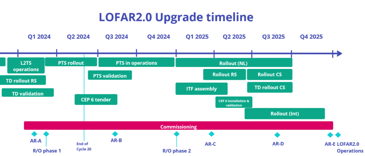
Multiple activities fall under AIVV, and this newsletter presents updates on all of them. The high-level plan for the upgrade is shown in the timeline, including the main milestones: the start of rollout phases (indicated by “R/O”) and the array releases (AR-A,B,C,D,E).
The next step is the upgrade of 2 stations: the Production Test Stations (PTS). The purpose of PTS is to prove that we can successfully build a LOFAR2.0 station; testing all steps in assembly, integration, and verification.
The verification tests in PTS will be used to determine if small modifications to the layout of the boards are still needed. Once these modifications are implemented, manufacturers will initiate production at a large scale.
First fringes with LOFAR2.0!
On February 1st, the signals from the first LOFAR2.0 station (CS001) were correlated with those from a LOFAR remote station (RS503) resulting in these fringes. These fringes represent a major milestone in the verification of the LOFAR2.0 hardware, firmware, and software.
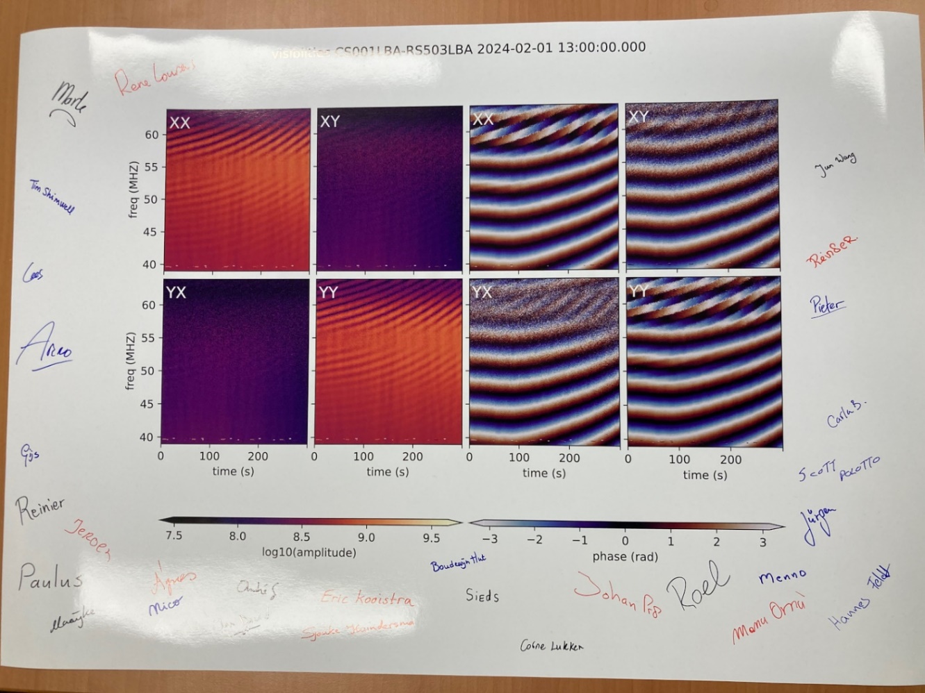
During this 5-minute observation, the new LOFAR2.0 hardware and firmware in CS001 – known as the LOFAR2.0 Test Station – was controlled by the new station monitoring and control system, with the observation on RS503 setup from within TMSS. The LBA_OUTER antennas were used to match the RS503 configuration and pointed to Cassiopeia A for this 5-minute test observation. The figure shows the amplitudes (lefthand 4 plots) and phases (righthand 4 plots) for the auto and cross-correlation products between CS001 and RS503. The phase plots show the phases drift with frequency and time, indicative of a yet-to-measure clock offset between CS001 and RS503, and variations in the ionosphere. The structure in the amplitudes is due to the active Sun coming in through the sidelobes of the stations.
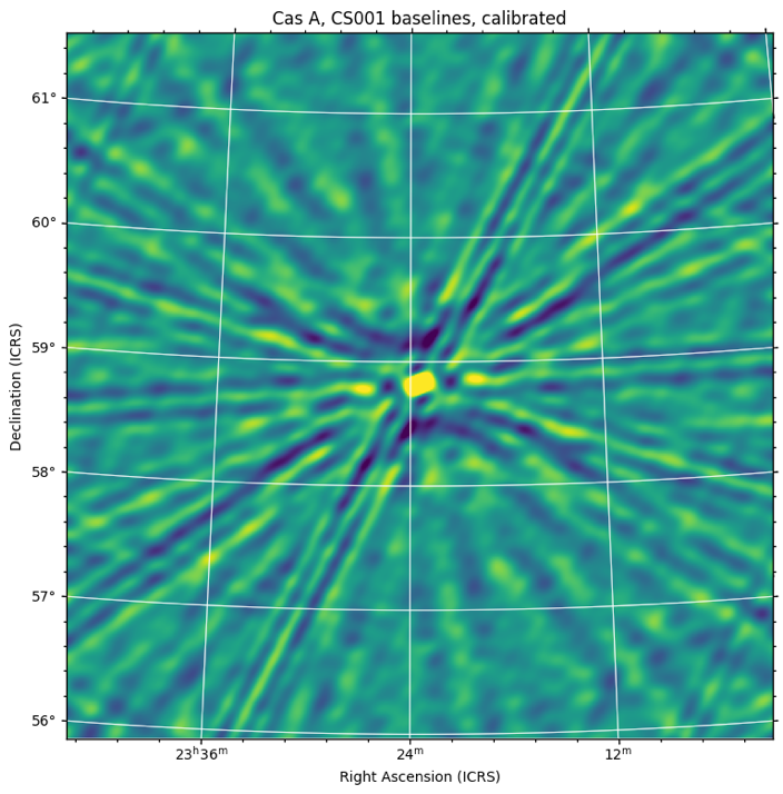
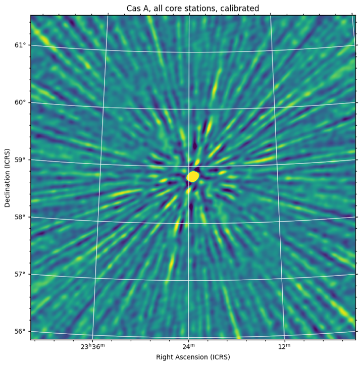
In a short follow up observation, the LOFAR2.0 test station was correlated with the other LOFAR core stations, allowing the visibilities to be imaged. The resulting images show that after calibration, Cas A is clearly visible in both the image using all baselines, as well as an image using only baselines using the LOFAR2.0 test station.
These observation ties together many of the LOFAR systems like the TMSS telescope management system and the COBALT correlator to the LOFAR2.0 station and confirms that the LOFAR2.0 subsystems involved in this observation operate as intended. These fringes are the result of the work of a large group of people at ASTRON, many of whom have already signed the poster showing the fringes.
Upgrade to the timing distribution system in the Netherlands
Currently in LOFAR, pulse per second (PPS) signals from an external GPS system are used to discipline a Rb-reference standard that generates 1 PPS and 10 MHz signals, both needed in the station signal processing. Each remote station has its own Rb standard, while core stations receive 10 MHz and 1 PPS signals via optic fiber (SyncOptics) from a central Rb clock.
One of the promises of LOFAR2.0 is to improve ionospheric calibration; which is closely dependent on clock accuracy. The improvement to the clock accuracy will be realized by replacing, in the Dutch array, the GPS-based timing distribution by a clock distribution based on White Rabbit (WR) technology. WR is an ethernet based system for data transfer and sub-nanosecond time transfer; it supports connection to thousands of nodes, many kilometers apart (typical distances of 10 km) with gigabit rate of data transfer and is fully open hardware, firmware, and software.
The WR based LOFAR2.0 solution distributes optically the 10 MHZ and 1 PPS signals from a single clock located at the Concentrator Node using WR switches equipped with optical transceivers.
During the first phase, the upgrade focuses on remote stations (RS) since they can be upgraded one at a time without creating major disruptions to regular LOFAR operations. Core stations (CS) are all connected to a single clock via the SyncOptics, therefore their upgrade cannot be done without interrupting LOFAR operations. They will be upgraded in a second phase, when the rest of the hardware in the stations will be replaced.
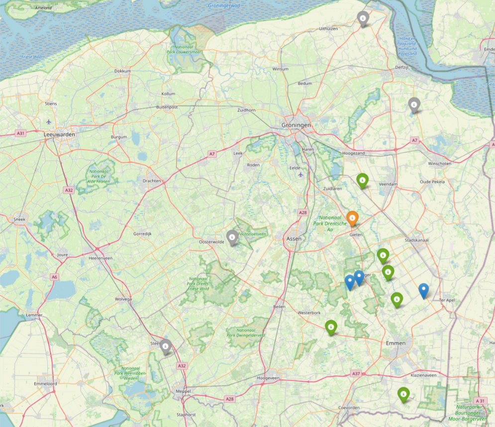
The first station was upgraded in November 2023, and new stations are added regularly.
The map shows the position of all remote stations, the color code indicates upgraded stations (green), a station where the WR is installed but not yet connected (orange), stations to be upgraded (gray and blue).
As part of the upgrade, a routine observation of 1-hr on a bright calibrator is done. The image shows an example of the clock drifts derived from such observation, for station RS205. The curve shows the clock drift between RS205 and the superterp. The drift observed is about 0.2 ns, remarkably below the requirement of 0.4 ns for observations of 1 hour.

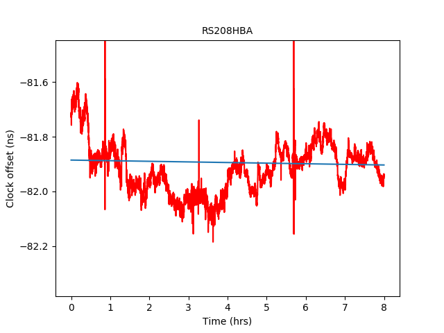
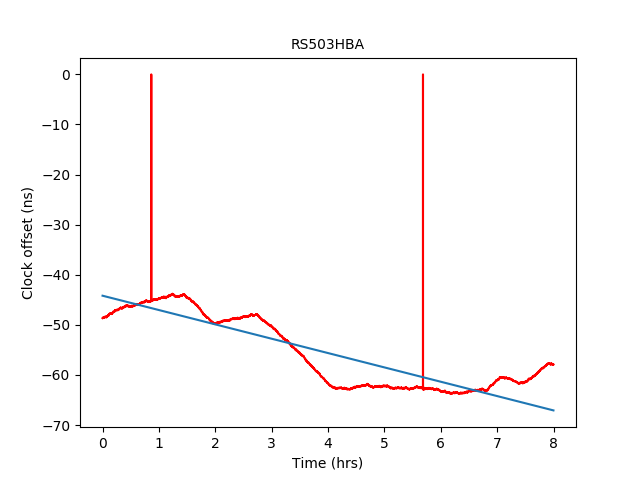
The following graphs show the clock drift comparison between a station with WR (RS208) and the non-WR station (RS503) where both are plotted with respect to the superterp, for an observation of 8 hours. Again, here the drift for WR is well below the requirement of 1 ns for 8-hour observations.
LOFAR2.0 Station Hardware
Most of the hardware development is now delivered, but there is still some work ongoing from the hardware team:
- The configuration for LOFAR2.0 of the international stations is slightly different than the stations in the Netherlands, the team has investigated those differences and is working on producing a Bill of Materials.
- The mechanical design for the station cabinet and the Bill of Materials was reviewed.
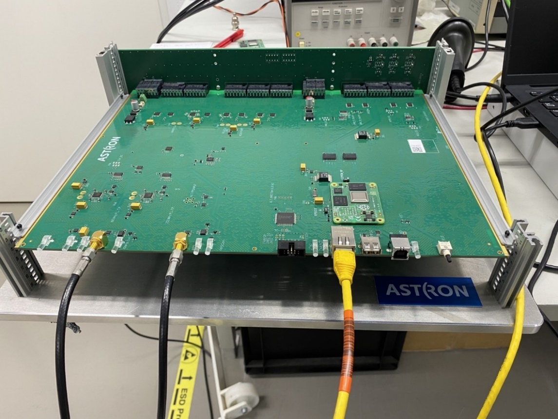
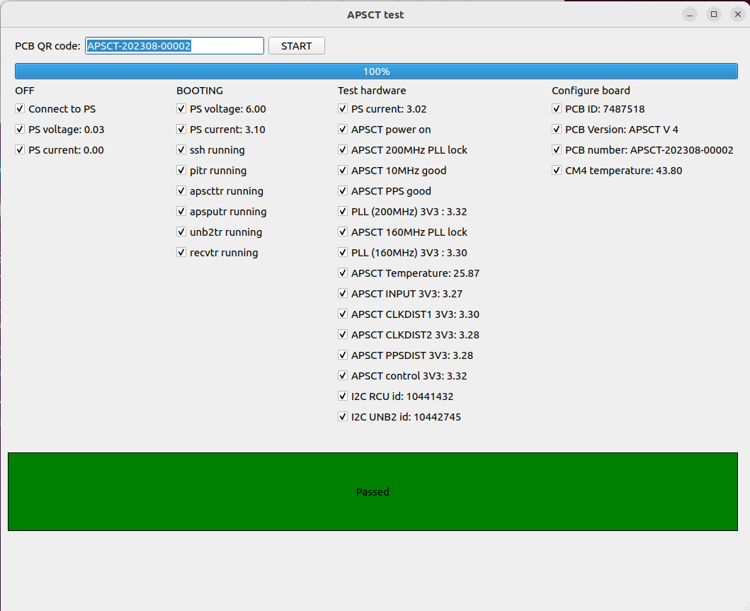
- Progress in the test setups is ongoing, as shown by the images showing the APSCT test setup and GUI.
Procurement & Rollout
- The electronic components for producing all existing plus two new LOFAR2.0 stations are secured and available.
- The Printed Circuit Boards (PCBs) have been produced for PTS, meaning two complete stations plus some spares.
- The Subracks and module front panels are currently produced after qualification of the prototype Subrack. Delivery is expected in February and March.
- This month, the PTS modules will be delivered and ready for integration in the Subracks and verification in the Integration Test Facility (ITF) in Dwingeloo and Westerbork.
- The procurement of LCU and power converters are waiting for technical approval from the engineers.
- An additional storage facility has been created in Westerbork and is ready to store the PTS hardware.
- eMaint has been prepared to include the new PTS hardware in the database.
- The rollout planning has been updated due to the late delivery of the various modules.
- Unfortunately, the manufacturer used a PCB material different from what was originally specified for the PTS RCU2H and RCU2L modules. We are working on a practical solution to minimize the project delay and cost. The “non-conformity board” has decided not to accept these RCUs and the manufacturer will need to replace the modules.
LOFAR Software Development
TMSS
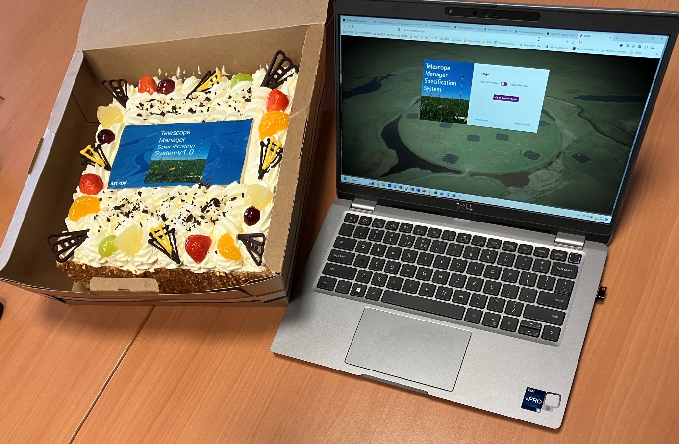
With TMSS v1.0 we have delivered a fully functional tool for Operators and SDCO. We are still finetuning some of the reporting capabilities and the quality assurance (QA) workflow, but in general all functionality that is needed is available. This is a major milestone, thence Team Ruby and its stakeholders celebrated the release TMSS v1.0 with cake at their last PI planning event in January (see picture).
The teams focus for TMSS is now put on some fundamental changes that are necessary for future maintainability and extensibility. This will require some refactoring of existing code, in order to be compatible with the latest releases of the underlying frameworks and libraries. Ultimately this will deliver TMSS v1.1, planned for May 2024. The current observing cycle 20 for LOFAR1 will end in June, after which focus will be on preparations for LOFAR2.0. After June, TMSS will be used much less active so we can spend development effort to support the development of the recently started proposal tool follow-up and to prepare for the changes that the LOFAR2.0 capabilities will bring to the system.
Station Control Software
We are migrating functionality from the single station based LCU to a newly acquired central server that will host the monitoring database and central control software for multiple stations. It has taken a while to get the server ready for this, but now that we have it, we intend to use it as soon as we can. The server software stack will be setup with Nomad and Consul, two technologies that will enable much more flexible handling of software deployment and dedicated network traffic control.
Meanwhile we are supporting the L2TS test station for validation observations and firmware updates. Together with the LOFAR Operators we are in the process of setting up Grafana-based monitoring dashboards for Operations; current dashboards have been set up for engineering purposes, mostly, which typically require more detail instead of a general high-level overview.
All other effort is aimed at providing the functionality to enable and automate the relative delay calibration of the antennas in a station’s antenna field. This is a feature that is seen as necessary once we have the PTS stations, so it is getting our highest priority. It will also automate and centralize recording of station statistics data which is vital for verification of the PTS stations during their rollout. Other Station-aimed activities of team Ruby are also focused on the needs for PTS rollout verification and later validation, as that is the most important and time-critical event to be happening in the nearby future.
LIFT
We have finished all work estimates for implementing the basic transient buffer functionality as required by LIFT. This includes firmware work and software work. These more detailed estimates indicate that we should be able to implement the functionality within the budget. What we will do next is to find a good time to start the work. This depends on factors like availability of enough LOFAR2.0 stations to execute realistic tests, availability of developers, and when the work fits best in the overall scheme of priorities. We now aim to start implementing firmware a few months before rollout starts, and software to follow the firmware effort with some weeks of delay. This planning can still change, though, as it is tightly coupled to the rollout planning.
SEE ALSO: