LOFAR2.0 Newsletter March 2021
Voila, here is the first LOFAR2.0 newsletter of 2021! It promises to be an exciting year for LOFAR2.0: In the Dwingeloo Test Stations (DTS) the LOFAR2.0 hardware, firmware and software will be linked together, and tested in the field for the first time. The data will be sent to COBALT2.0. After years of hard work, it will be a great reward to see the data flowing! The DTS will tell us what is already working, and most importantly, where more work is needed. Another highlight of 2021 will be the Critical Design Review (CDR) of the Timing Distributor, demonstrating that it is ready for procurement and rollout. I cannot wait to see (and celebrate!) the results.
The process to resolve the budget issues in LOFAR2.0 has almost concluded. The final decisions will be made at the ILT Board meeting on March 31st. In January, it was already decided that a switchable filter will be added to the HBA-LOW band to in- or exclude the 170 – 190 MHz frequency range, and that the hardware enabling the HBA-MID mode (170 – 230 MHz) will be installed. Pending decisions concern the transient buffer, the station output data rate, and in what way the LOFAR1 stations will be supported during the first years of LOFAR2.0 operations. Over the last two months, many disciplines have been consulted (science, operations, maintenance, development) to ensure that all pros and cons of the choices have been taken into account.
Happy reading, and have fun this year!
Systems engineering
Early Integration of the Dwingeloo Test Station
We need to integrate the LOFAR2.0 system into the operational LOFAR1 system. LOFAR is a complex system, so integration is full of risk. Combined with stringent budget and time constraints the challenges are even more severe. Still, the upgrade to LOFAR2.0 is a chance to make it easier to use and operate the LOFAR telescope. To reduce risks early in the program we will integrate the Dwingeloo Test Station into a limited end-to-end system as early as possible.
By quickly implementing a chain “from antenna to scientist” and “from antenna to operator”, we will involve all teams to work towards a first integrated system. The Dwingeloo Test Station will be integrated with other sub-systems like Timing Distributor, Central Processor, Network, Telescope Manager and Operational Processes. This will allow early verification of key functionality. For example, as part of setting up the full chain, it will be verified that the central processor is able to read the LOFAR2.0 station data. It will also allow early validation by users: an example is that the operator can validate the graphical user interface to operate the limited system.
The sooner we have an integrated end-to-end LOFAR2.0 chain, the sooner we identify unforseen issues. If it is needed to adapt the design because of this, we can do so at a stage when it is relatively easy and cheap.
|
|
Station
RCU2 developments
The receiver team is working on the qualification boards for RCU2L, which will have the filters and the ADC part integrated in a single board. These boards will then serve as the new prototype board for the DTS and for external production later.
On the high band RCU2, a switchable filter is added to suppress RFI from the DAB-band between 170-190 MHz. This was a decision made by the ILT board in January. As a result, a new round of engineering has been started to accommodate such a switch and filter on the final boards. First, a separate small switchable filter has been designed, build, and tested at ASTRON, and currently the design is integrated in the RCU2H model by INAF to test the impact on the board as a whole. The addition of the switchable filter will lead to a somewhat longer delivery time of the RCU2H board, which we will accommodate by first testing and validating the low-band signal chain.
Firmware developments
There is good progress in the joint effort to implement the SDP ring functionality of the Uniboards in OpenCL, instead of VHDL. If truly successful, this would be the first use of OpenCL in an FPGA environment in a production system for ASTRON. The expectation is that by using OpenCL, the FPGA firmware development time can be shortened radically. The project is carried out by Reinier van der Walle and funded by John Romein’s Triple-A 2 project. It demonstrates how two projects can be of mutual benefit, and of benefit for ASTRON as a whole.
Lab Test Station
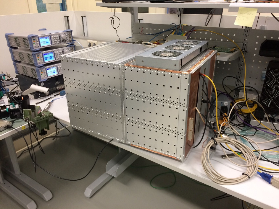
The Lab test station (LTS) is still running as our functional integration test platform. For testing noise characteristics of the RCU2s it had to be embedded in a Faraday cage (see Figure 1). This was needed to carefully measure noise numbers while being inside the lab. The measurements were successful and led to the conclusion that the measured noise is now compliant with the requirements.
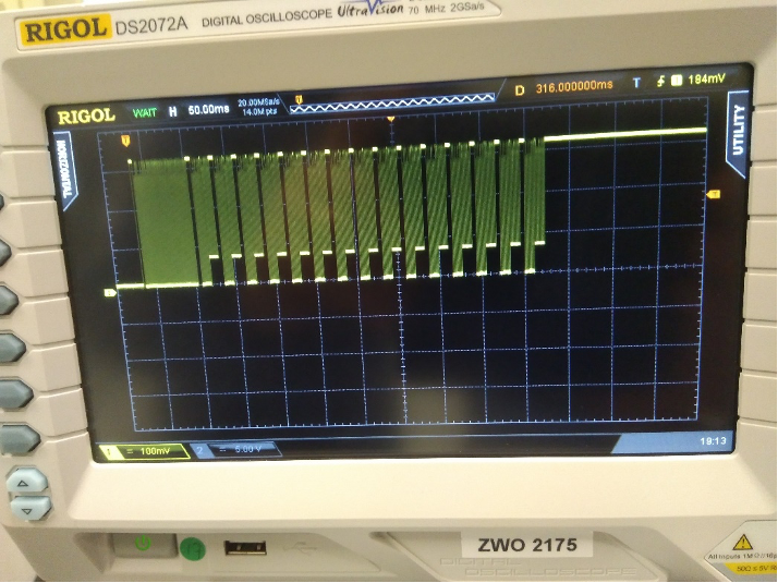
Furthermore, we have proven that we can control the HBA tiles in the Dwingeloo garden through the RCU2s in the LTS, which is yet another important milestone for the project (see Figure 2).
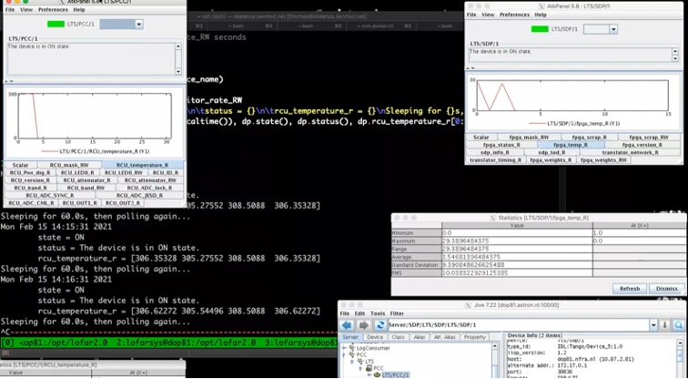
Station Control, together with the SDP and RCU group, is continuing to work on monitor and control of the Uniboards and RCUs using the TANGO framework. In Figure 3 you can see a screenshot of a polling client to the RCU2 python translator (exposing an OPC-UA interface) on the left. The translator in turn requests status data from four RCU2s via I2C. Also shown, on the right side, is a request for similar information from the SDP translator which is connected to the firmware running on the Uniboard2 in LTS.
The foundation being laid by SC in this way is gaining solidity through prototyping and testing like this. Essential to further progress are more detailed ICD documents, an effort which is time consuming but will continue with great effort.
Dwingeloo Test Station
The big dot on the project’s horizon is the Dwingeloo Test Station (DTS). The DTS is a small station prototype in real environmental conditions, placed in a LOFAR cabinet at the ASTRON test field. It will have significance all over the LOFAR2.0 program, as it integrates the work of Station and TD, but also it will be connected to CEP and COBALT2, we plan early commissioning and science activities, and see an important role for training Operations of LOFAR2.0. This makes DTS much more than a simple testbed for station hardware. Still, before all that can materialize, we first need all bits and pieces to be available, placed connected and tested. Therefore, many activities in the project are directed to delivery of the DTS.
One of the early tests, carried out partially in the lab, and partially in the DTS cabinet is related to validating the cooling capacity. LOFAR1 has serious problems with cooling especially on hot summer days. By both, thermal modelling and carefully guiding the airflow through the new subracks, and allowing for a higher maximum temperature in the subrack cabinets, we hope to achieve better results. Furthermore, TO is planning to install sunroofs above all NL cabinets to shield them from solar irradiation. The DTS will be equipped with a similar sunroof, so that all our tests will be run in comparable circumstances.
Timing Distributor
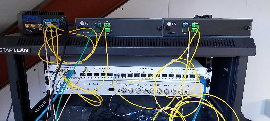
Last December, Santa brought some presents to the Timing distributor team. In the picture you can see our good old White Rabbit switch (bottom), and on top of it the brand-new multiplexers, in this case the DWDM (dense wavelength division multiplexer). DWDM technology works by combing and transmitting multiple signals simultaneously at different wavelengths over the same fiber. The different wavelengths are combined in a device called a Mux, where the optical signals are multiplexed (and de-multiplexed).
The picture shows the current setting in a home-laboratory where we are testing the stability of the connection using a 10km fiber (not visible, but actually lying on the ground below). This test is needed to prepare for the next step. In collaboration with Telescope Operations, our team designed a series of tests to be done in the LOFAR field. Now we are waiting for the green light from our colleagues at Telescope Operations (and the bad weather to stop) to install the new equipment in the selected stations. After completing the measurements, the white rabbit switches will be disconnected again from the LOFAR stations.
LOFAR2.0 Procurement
Phase-1 of the Uniboard2 production is running and expected to deliver two prototype boards in April. In phase-2, six boards will be produced ready for populating the sub-racks of Prototype-Test-Station (PTS). Finally, phase-3 will deliver Uniboards for the LOFAR2.0 rollout.
We are still in the development phase but the procurement activities are already focussing on the procurement of the other equipment, both commercial off the shelf (COTS) as well as the specific LOFAR2.0 developed equipment. In order to reduce risk, we will as much as possible identify the manufacturers and suppliers that deliver the equipment for both the PTS and for the LOFAR2.0 rollout phase. Since a procurement process takes about 3 to 6 months and board production about 4 months, it is important that procurement details are available as soon as possible in order to start the procurement process and to be ready for the PTS production. In the next period, engineers and managers will be requested to provide the procurement information.
LOFAR4SW
The LOFAR4SW team completed the second periodic report on January 30, submitted on time to the EC. Now our team can focus on the final year of the project, we are exactly 12 months away from the end. In the coming months the activities will ramp up, since the critical design review is quickly approaching (September 2021).
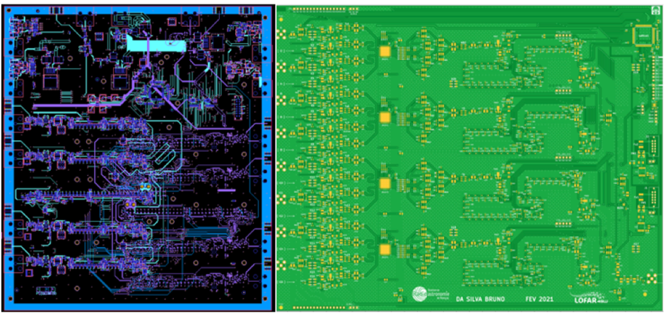
The picture on the left shows the printed circuit board CAD design of the dual beamformer board designed by our team for the HBA tile prototype. It contains delays and control circuitry for 4-dual polarized antenna elements. The current layout was recently reviewed. After solving the comments and issues identified, the board will be ready for production.
In parallel, a beamforming board including ASIC was developed by our partners in Nançay and was recently sent to production (see picture on the right side). The time delay in the board is organized as follow: a 1st group integrated on ASICs and a 2nd group done with inductance etched in the PCB. The board includes all necessary components such as RF path, control/monitoring and DC power filtering. The size of the PCB is 29×24 cm. Two nested boards can handle 16 antennas (one HBA tile) creating dual beam for one polarization; 4 boards per tile are sufficient to have dual beam per HBA tile on station.
COBALT2.0 phase 2
Cobalt 2.0 is currently on (planned) hiatus and will continue with its final development phase from April.
TMSS
ASTRON is developing TMSS (Telescope Manager Specification System), which is a brand-new software application for the specification, administration, and scheduling of LOFAR observations. It will enable the required support for LOFAR2.0 use cases, while also streamlining LOFAR operations and improving the adaptability and maintainability of software for future extensions.
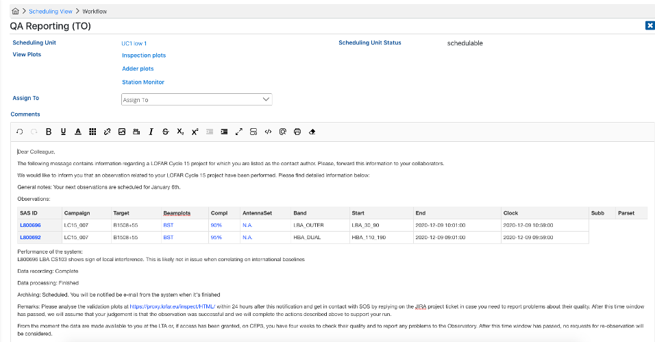
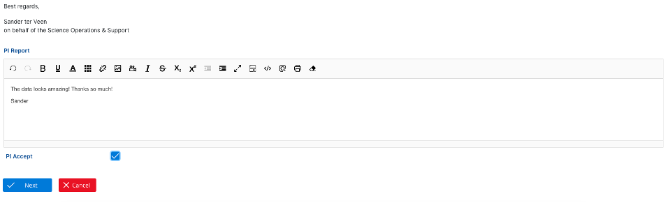
Work has progressed on the quality assessment workflow in TMSS, which will streamline the reporting of observations to the project investigators (an example of the QA reporting interface is shown in the figure), the ingest, dynamic scheduling and adjusting the GUI with all new features added. The first dynamically scheduled observations have run and commissioning is in progress.
Two current focus areas for the further development are adding support for beamformed observations and pipelines and adding constraints and priorities to the dynamic scheduler. The development plan of TMSS is right on track: TMSS will be put in production in June 2021, at the start of cycle 16. A second phase of TMSS development will start after that to support more science use cases and realize further streamlining of the operational processes.
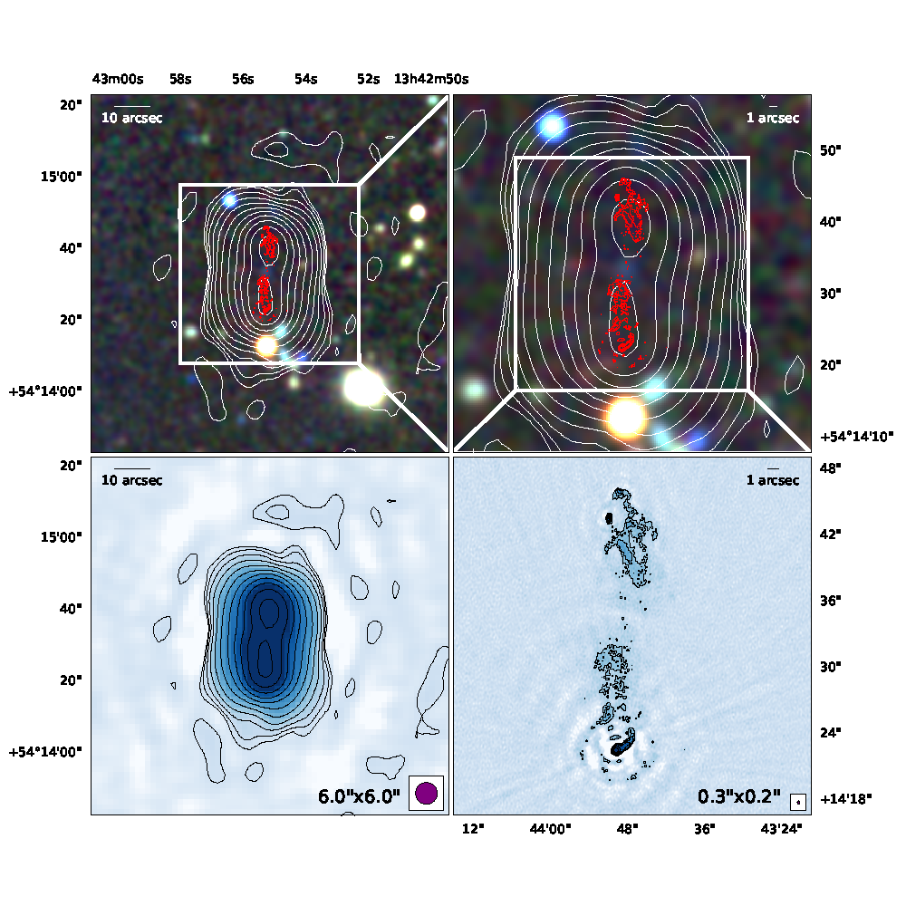
Sub-arcsecond imaging with the International LOFAR Telescope
Over the past two months, the LOFAR Long Baseline Working Group (LBWG) has been busy preparing scientific papers using the full array of the International LOFAR Telescope (ILT) to achieve sub-arcsecond resolution. These papers will be part of an upcoming special issue of Astronomy & Astrophysics, and will showcase this unique LOFAR capability. Included in the special issue will be a paper describing the foundational calibration strategy and the challenges inherent in high-resolution imaging at low frequencies, a paper on the completed Long Baseline Calibrator Survey, and nine other papers with exciting scientific results. The scientific papers, which are mostly student-led, cover a range of topics from powerful radio jets in distant AGN to colliding galaxies. The image shows the factor of 20 improvement in angular resolution by using the ILT versus only the part of the array in the Netherlands, for a powerful FRII radio galaxy.
Warning: Undefined array key "show_parent_page_in_sidebar" in /srv/www/wordpress/wp-content/plugins/oxygen/component-framework/components/classes/code-block.class.php(133) : eval()'d code on line 10
SEE ALSO: