LOFAR2.0 Newsletter September 2020
Many of us enjoyed a well-deserved summer leave. I hope you had a good and relaxing time. In the meantime, work on LOFAR2.0 design steadily progressed. As you will see in this Newsletter, the new LOFAR system is getting shape and an increasing number of prototypes is appearing on the benches. Happy reading!
Architecture
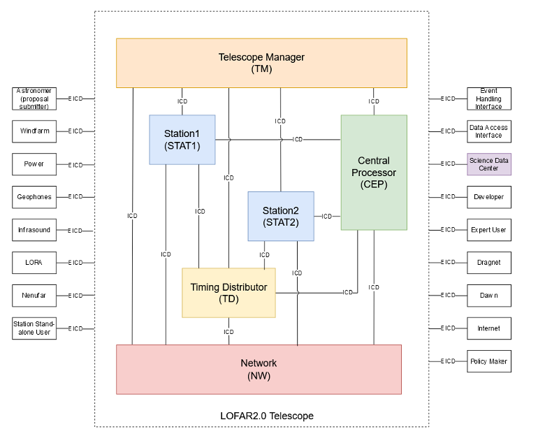
Although a lot of work is done in developing and accommodating LOFAR2.0 stations within LOFAR, also LOFAR1 stations need to be supported. For this, a design decision document was written and since then a new sub-system is added to the LOFAR2.0 architecture as depicted in Figure 1: the Station1 sub-system. The solution chosen is to hide the LOFAR1 station with a wrapper, such that other systems can interact with the LOFAR1 station with “just” another configuration. In due time a project needs to be started to realise the LOFAR1 station wrapper. By this elegant solution, the renewed Telescope Manager system for LOFAR2.0 can already be used when the wrapper is available, prior to the roll-out of LOFAR2.0 stations.
COBALT2.0 phase 2
The COBALT2.0 Phase 2 project is currently halted (as planned). The next sprint will start mid-September.
Timing Distributor
The Timing Distributor project had a severe delay because the 1 PPS signal from the White Rabbit switches was too weak to trigger the station timing. Just before the summer vacation we successfully produced and tested a module (“pulse shaper”) to solve this issue. We have built this solution into remote stations RS307 and RS208. Then we did a test observation. The system was stable and the first results look good.
In parallel, we purchased a few WR-LEN White Rabbit nodes from Seven Solutions. These are much cheaper than the OPNT switches. We are evaluating if these nodes fulfil our requirements.
LOFAR4SW
The LOFAR4SW team recently finalised the use cases prioritisation, thanks to the input obtained at the successful online End Users Workshop last May (see previous newsletter).
Our partners in UKRI (leading WP4 System Design) completed successfully the installation of the test station in Chilbolton (902C), that is now operational. Given the strict restrictions to access the site during the last couple of months, reaching this milestone was challenging. The test station consists of 4-HBA tiles and it will be used to test software, mainly pipelines, that are being developed in WP6 Software Design (led by Chalmers). The team is now working on a plan for the tests that will be done.
On the hardware development, the work is now focused on the development of the beamformer prototype. We expect that the development phase will be finalised at the end of September when building and assembly will start.
Small blocks of the required functionality for the HBA beamformer were developed, assembled and tested. The simulations and measurements show good results and only minor adjustments are required to start integration of the building blocks into the full beamformer board design.
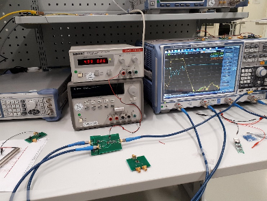
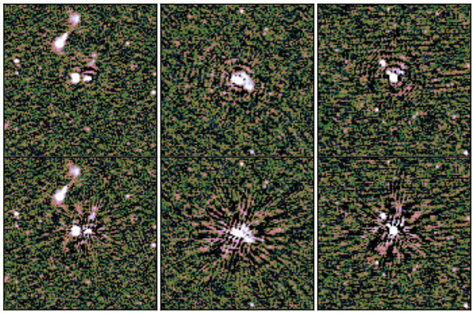
The image shows the measurement setup and results of the first active splitter prototype including a bandpass filter to reject AM and FM frequency bands on the low side and DAB, DVB-T on the high side. The two traces (blue and red) show the response of the first section of the two-receiver chain that will provide two analogue beams, a nice inband agreement is visible.
On the management side, the consortium decided to request an extension of 9 months to the EC, pushing the Critical Design Review to September 2021 (instead of the original date planned, February 2021). The change is necessary to compensate for the delays suffered due to Covid-19, in particular in the hardware and system design. The project’s General Assembly has formally decided to go on with the request, that is now being prepared for submission to the European Commission.
 |
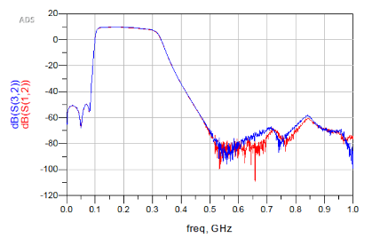 |
Left: measurement setup of the active splitter. Right: Measurements of the active splitter.
Station
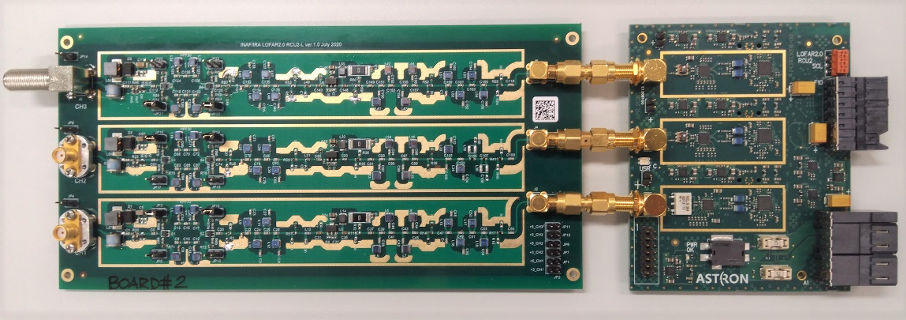
First RCU2-L prototype board
We have completed the first RCU2-L (low band) prototype, where the analogue chain (left PCB with filters and amplifiers in Figure 1) was developed by INAF and the digitization side (right PCB in Figure 1) by ASTRON. The purpose of the prototype is to verify our simulations and to find problems before integrating it into a single RCU2 PCB. And with more than 600 components on the two PCBs, we are pleasantly surprised by the small number of issues we had, most of which could be solved on the prototype PCB to give us a working prototype. Lab measurements show the prototype to behave largely as expected.
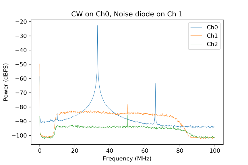
Setting up the Lab Test Station
In the digital lab in the ASTRON, we are setting up the first receiver chain using prototype boards. Figure 2 is a picture of the current setup. On the left, an input signal enters the first RCU2-L prototype board (laying upside down), then the filtered signal goes to the ADC and from there directly into a Uniboard2b for acquisition. Using this setup, we have been able to capture the first filtered and digitized signals on the Uniboard, a major step forward for the team!
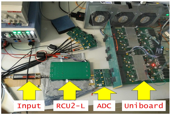
Figure 3 shows a measurement using the 3 separate RCU2 channels. Channel 0 had a CW tone applied for dynamic range testing, channels 1 had a noise diode for testing the passband and channel 2 had no input, to measure gain and sensitivity.
Further testing on this test setup continues, which will eventually lead to an improved version of the RCU2-L boards. All test runs are administered in Polarion. Finally, a prototype RCU2-H, the high band receiver, is currently manufactured by INAF.
Subrack design
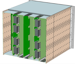
We are currently investigating heat dissipation, power consumption, cooling, airflows, cable layouts, and maintenance aspects of the new subrack design. Together with the planned sunroofs for the LOFAR cabinets, this should lower the number of days LOFAR stations switch off in summer as a result of lack of cooling capacity. Figure 4 shows a drawing of a subrack containing the Uniboards (left), and a simulation of the temperature of the components and the airflow cooling it from below (right).
 |
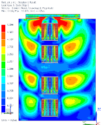 |
Figure 4: Subrack design drawing and simulation showing the temperature of components and airflow
Control firmware and software
The software architecture that has been delivered early July is under review. More details will be added to this architecture and design in the coming period. Meanwhile, prototype monitor and control software devices are written for the LTS. The interface software for the Uniboards is well underway, as is a first version of control for the RCU2s that will be hosted by a microcontroller.
The best possible system upgrade for LOFAR
We are ambitious in making the best possible system for the astronomical community. With our stakeholders, a lot of candidate system improvements are identified. That results in a long list of requirements that need work and hardware, firmware or software to be implemented. However, the available budget and time in the project is limited. If it is not clear what will actually be delivered at the end of a project, we may implement the wrong functionality first.
Such deviation between expectations and reality is a problem as, when the projects are finished, the system will not allow scientists to do the science that is considered the most important. To resolve this, we have started the approval process of the LOFAR2.0 requirements: Requirements will be approved or disapproved based to explicitly define the scope of the Stage 1 delivery. This provides clear guidance for the developers and greatly reduces the chance of building the wrong system for the scientist.
So by going through the approval process, the LOFAR system will have the best possible upgrade and will continue to allow scientists to make astronomical discoveries happen!
Differential Total Electron Content (DTEC)
Joshua Albert
Over the past year, we have implemented an idea that is years in coming: non-diffractive tomographic ionospheric calibration. We begin with precisely calibrated Jones scalars in several dozen directions over the field of view on a time resolution of 30 seconds. From these we must accurately infer the differential total electron content (DTEC), that iniquitous physical quantity that provides a measure of the projected effect of the disturbing medium we call the ionosphere. We apply a recursive Bayesian method, which does a fair job of recovering physically meaningful DTEC. From these DTEC we use a novel probabilistic tomographic model to infer the DTEC for every moderately bright source in the field of view. The resulting images have inter-calibrator direction dependent errors equivalent to doubling the integration time. We call this a win! And, acknowledge there is room for improvement (think LOFAR2.0). An interesting result is the zoo of ionospheric screens.
TMSS
Roberto Pizzo
TMSS (Telescope Manager Specification System) will be a brand-new software application for the specification, administration, and scheduling of LOFAR observations. it will enable the required support for LOFAR2.0 use cases, while also streamlining LOFAR operations and improving the adaptability and maintainability of software for future extensions.
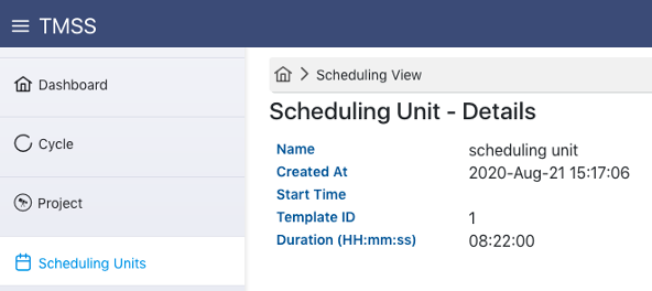
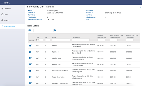
The TMSS project has made progress in various areas. The web interface is now taking shape (see figures). It is already possible to view and edit cycles, projects and tasks, and soon it will be possible to specify a complete scheduling unit (the combination of observations, pipelines and quality assurance plots) in one go. Through TMSS it is now possible to run a full scheduling unit (specified in the backend) and a concrete start has been made with dynamic scheduling, a revolutionary system that will automatically determine the observing schedule.
Work is in progress to complete the observing chain by adding the specification of ingest jobs. While work will continue on dynamic scheduling, frontend, and backend, a test version of TMSS will be installed coming October for commissioning purposes. According to the current planning, TMSS will be put in production in June 2021, at the start of cycle 16.
 |
 |
SEE ALSO: